
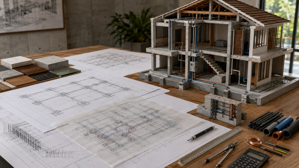
Most people assume that construction work can begin immediately following approval of the floor plan and 3D visualisation. The architectural concept only shows how the structure is arranged and designed. There are certain technical aspects of the architecture that are not included.
The plans need to be translated into structural and MEP drawings before construction can begin. The structural drawings show the foundation, columns, beams, slabs, staircase, and roofing of the structure. MEP drawings will include details of ventilation, air conditioning, drainage, water supply, electricity, and other building services.
The two drawings are very important as most of the costly construction mistakes come from improper coordination between structural elements and building services, and not from poor aesthetics. For instance, a drainage pipe may end up on the front elevation, a beam may obstruct an air-conditioning route, a column may interfere with the furniture layout, or an electrical socket may be hidden behind a built-in cupboard.
From Our Project Experience
In residential projects, some of the most important coordination checks happen before construction begins. For example, aligning structural columns with walls, concealing AC drainage routes, coordinating electrical points with the furniture layout, and ensuring rainwater pipes do not interfere with the main façade.
1. What Are Structural and MEP Drawings?
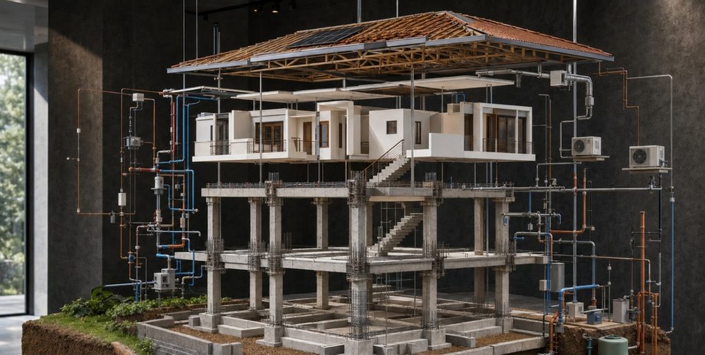
Structural drawings explain how the building will safely carry and transfer loads into the ground. They typically cover:
- Foundations
- Footings
- Ground beams
- Columns
- Beams
- Floor slabs
- Staircases
- Retaining walls
- Roof structures
- Reinforcement details
- Structural connections
MEP drawings stand for Mechanical, Electrical, and Plumbing. For a Sri Lankan family house, MEP may include:
- Electrical wiring and power outlets
- Lighting
- Distribution boards
- Earthing and lightning protection
- Air-conditioning
- Mechanical ventilation
- Water supply
- Hot-water systems
- Wastewater drainage
- Rainwater drainage
- Septic or sewer connections
- Water tanks and pumps
- Solar-energy provisions
- Communication and security systems
2. How Are These Drawings Different from the Architectural Plan?
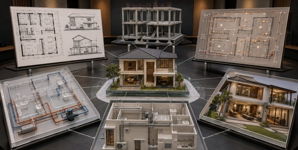
Homeowners often assume that one drawing contains everything. It doesn’t.
| Drawing type | What it explains |
| Architectural drawings | Room layout, dimensions, doors, windows, elevations, and appearance |
| Structural drawings | How the building will stand safely and transfer loads |
| Electrical drawings | Lighting, sockets, circuits, power supply, and electrical equipment |
| Plumbing drawings | Water supply, sanitary fixtures, wastewater, and drainage |
| Mechanical drawings | Air-conditioning, ventilation, pumps, and mechanical equipment |
| 3D visualizations | How the proposed spaces and finishes may look |
All of these drawings describe the same building from different professional perspectives. Before construction begins, they need to be coordinated so that the architectural, structural and building-service requirements agree with one another.
3. Why Structural Design Should Begin Early
Structural design should be considered early in the design process. If it is left until the architectural layout is almost complete, changes to columns, beams, foundations, and other structural elements may affect both the appearance and cost of the house.
Columns, Beams, and Foundations
- Column positions: Columns should ideally work with the walls, corners, and general floor layout. Planning them early helps avoid columns appearing in inconvenient places once the architectural design has already been developed.
- Beam spans: Longer spans usually require larger or deeper beams. This can increase material costs and may also affect ceiling heights. Early coordination can help keep beam spans practical where possible.
- Column alignment: Keeping columns aligned between floors generally makes the structure simpler. If columns change position from one floor to another, additional structural work may be required to transfer the loads.
- Foundations: The size and type of foundation depend on the loads coming from the building and the ground conditions. Considering these early helps the engineer design the foundation correctly from the beginning.
Features That Affect the Structure
Some architectural features need more structural planning than others.
- Large open-plan areas: Living and dining spaces without many columns may need longer or deeper beams. These spaces should be discussed early so the design remains practical without losing the open feel.
- Cantilevered balconies: Balconies without visible supports need additional structural design and reinforcement. It is much easier to allow for this during the initial design stage.
- Double-height spaces: Double-height areas change the usual arrangement of floors, beams, and columns. Because of this, they should be included in the structural planning from the start.
- Rooftop water tanks: Water tanks become very heavy when filled. Their position and size should therefore be known early so the roof structure can be designed to carry the load safely.
- Swimming pools: Pools add considerable weight and also require proper waterproofing and structural detailing. Their location should be decided before the surrounding structure is finalised.
Site Conditions and Future Changes
Structural design should also take into account the site itself and any future plans for the house.
- Future upper floors: If another floor may be added later, the foundations and columns should be designed to carry that additional load from the beginning.
- Retaining walls: Sloping or uneven sites may require retaining walls and different foundation solutions. These can have a major effect on both structural design and construction cost.
- Complex roofs: Unusual roof shapes or roofs with several different levels may need additional beams, supports, and structural detailing. Early coordination can help keep the design practical and cost-effective.
Some architectural ideas will naturally require larger beams, additional columns, or more complex structural solutions. This does not mean they cannot be built. However, it is better to understand these requirements while the design is still being developed, so the architect and structural engineer can work together to find a suitable solution.
4. What to Check in Foundation Drawings
The correct foundation system depends on the building, soil, and site conditions. When reviewing the foundation drawings with your engineer or architect, pay particular attention to:
- Type of foundation proposed
- Footing locations
- Foundation depths
- Ground-beam arrangement
- Relationship with boundaries
- Differences in ground level
- Retaining-wall requirements
- Foundation near existing structures
- Provision for future floors
- The engineer’s soil-related assumptions
- Whether a soil investigation was carried out
There’s no such thing as a one-size-fits-all foundation detail, it should reflect your specific site.
5. What to Check in Column, Beam, and Slab Drawings
Worth a look:
- Whether columns interfere with rooms
- Whether columns project awkwardly from walls
- Alignment of columns between floors
- Beam locations and depths
- Beams crossing windows or doors
- Beams affecting ceiling heights
- Floor-slab thickness
- Cantilevered areas
- Staircase support
- Roof-slab requirements
- Openings through slabs
- Water-tank support
The structural engineer is responsible for determining member sizes and reinforcement. As a homeowner, your main concern is whether the proposed structure affects the usable space, ceiling heights, openings or appearance you have already approved.
6. Why Structural and Architectural Drawings Need Coordination
A few practical examples of what coordination catches:
- An architectural plan shows an open living room, but a structural column appears in the middle
- A beam reduces the intended height of a large window
- A staircase looks correct in plan but lacks sufficient headroom under a beam
- A balcony edge doesn’t align with its supporting structure
- A water tank is shown on the roof without adequate structural support
- A plumbing opening is required through a structural beam
These conflicts should be resolved between the architect and engineer at the drawing stage not improvised by workers on site.
7. What Should Be Included in the Electrical Drawings

Main elements typically covered:
Power and distribution
- Main connection
- Meter
- Distribution board
- Earthing
- Lightning protection
Lighting and outlets
- Lighting points
- Switches
- Sockets
- Appliance outlets
Future systems
- Solar
- Battery
- EV charging
- CCTV
- Internet/data
For Sri Lankan homes, it’s worth factoring in future solar panels, inverter systems, backup power, and EV charging at the design stage rather than retrofitting later.
8. Review Switches and Sockets Against Furniture
A technically complete electrical drawing can still be inconvenient if it isn’t coordinated with the interior layout. Worth checking:
- Bedside sockets are accessible
- Switches aren’t hidden behind doors
- Television points align with the television wall
- Kitchen sockets sit above usable counters
- Refrigerator and appliance outlets are accessible
- Study tables have sufficient power and data points
- Air-conditioner points suit the final unit positions
- Outdoor sockets are properly located
- Bathroom outlets and equipment are positioned safely
- Built-in cupboards don’t cover electrical points
This is exactly the kind of check that pairs well with the furniture-scaled 3D model from the earlier stage of your project..
9. What to Check in Water-Supply Drawings
The water-supply design should show more than simply where taps and bathrooms are located. Check that it also addresses:
- Incoming water connection
- Water-meter position
- Underground water storage
- Overhead water tanks
- Pump locations
- Pipe routes
- Isolation valves
- Water pressure
- Hot-water supply
- Kitchen connections
- Bathroom connections
- Washing-machine points
- Garden taps
- External washing points
- Future maintenance access
Water tanks and pumps should sit where they can be maintained without excessive noise or damage to the building’s appearance.
10. What to Check in Drainage and Sewerage Drawings
Particularly important in Sri Lanka, given heavy rain and varying sewer infrastructure across areas. Review:
- Wastewater pipe routes
- Soil pipes
- Floor traps
- Inspection chambers
- Manholes
- Septic-tank position, where required
- Soakage arrangements
- Public sewer connection, where available
- Kitchen wastewater
- Bathroom drainage
- Pipe gradients
- Vent pipes
- Access for maintenance
- Separation of rainwater and wastewater systems
Depending on what is available in your particular area, the National Water Supply and Drainage Board’s sewer-connection procedure requires a scaled underground sewer-plumbing plan.
11. Plan Rainwater Drainage for Sri Lanka’s Monsoons

Sri Lanka’s periods of intense rainfall make roof and site drainage an important design consideration, particularly on sites with limited falls, neighbouring properties at different levels, or restricted discharge points. Therefore, also include:
- Roof gutters
- Downpipes
- Rainwater outlets
- Surface drains
- Balcony drainage
- Courtyard drainage
- Driveway levels
- Site gradients
- Road-drain connections
- Rainwater harvesting
- Discharge away from foundations
- Prevention of water entering neighbouring properties
- Overflow arrangements
- Maintenance access
A visually attractive house can still develop serious problems if roof and site drainage are treated as an afterthought.
12. What Falls Under Mechanical Drawings in a House
Mechanical services in a typical house are less extensive than in a commercial building, but poor coordination can still affect ceilings, façades, maintenance access and everyday comfort:
- Air-conditioning unit locations
- Refrigerant-pipe routes
- Condensate drainage
- Outdoor compressor units
- Bathroom exhaust fans
- Wet-kitchen extraction
- Cooker hoods
- Mechanical ventilation
- Water pumps
- Hot-water equipment
- Swimming-pool equipment, if applicable
- Generator or inverter ventilation
Outdoor AC units shouldn’t obstruct walkways, appear prominently on the front façade, or discharge heat into poorly ventilated areas.
13. What the homeowner should visually check with the 3D Design
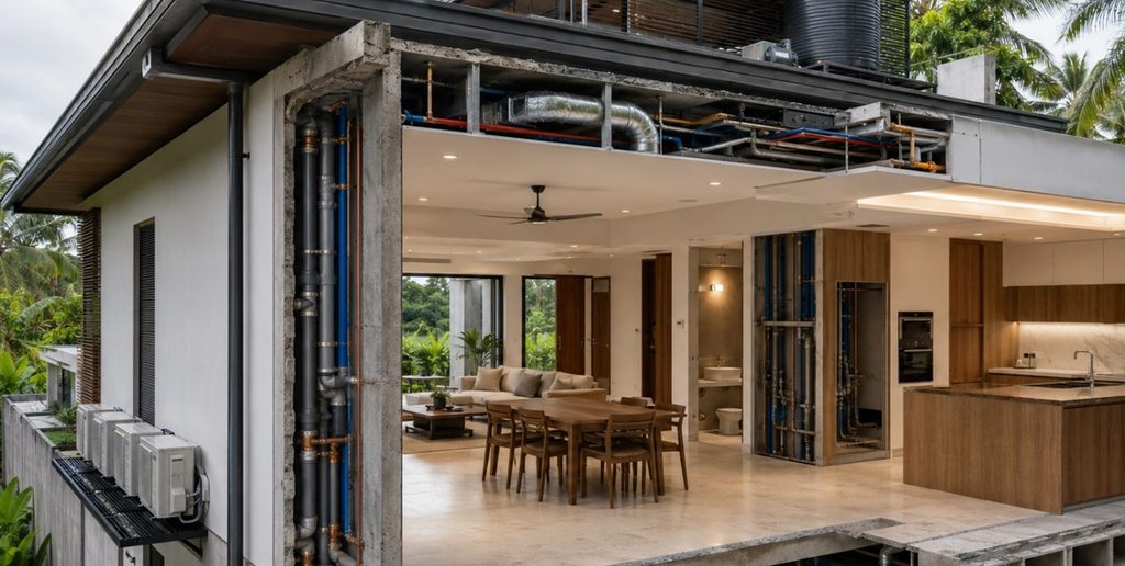
This ties directly back to the 3D visualisation stage of your project. A coordinated design should reveal:
- Drainage pipes on exterior walls
- Air-conditioning units on elevations
- Bulkheads required to conceal services
- Ceiling heights after service installation
- Plumbing shafts
- Access panels
- Lighting positions
- Water tanks and pumps
- Roof penetrations
- Conflicts between pipes and beams
- Conflicts between lights and ceiling fans
- Conflicts between services and built-in furniture
A coordinated 3D model can become a useful design-review tool when major structural and service elements are represented alongside the architectural design, rather than showing only furniture and finishes.
14. What do MEP Coordination Drawings do?
Individual drawings can each look correct while still conflicting with one another. Coordination drawings combine the relevant information to catch:
- Pipes crossing beams
- Ducts interfering with structural elements
- Electrical conduits conflicting with plumbing
- Lights positioned below beams
- Ceiling fans conflicting with lighting
- Plumbing shafts cutting through cupboards
- Drainage pipes appearing on important elevations
- Service routes becoming inaccessible
- Insufficient ceiling space
This process is sometimes called clash detection, particularly where a coordinated digital or BIM model is used.
15. Why Openings and Sleeves Should Be Planned Before Concreting
Plumbing pipes, electrical conduits, air conditioning lines, rainwater outlets, drainage pipes, exhaust ducts, and service shafts may all need openings. This is a useful aspect to comprehend.
Workers may later have to drill or cut into structural components if these aren’t anticipated before slabs and beams are cast. Any proposed drilling, cutting or alteration of a structural member should first be reviewed and approved by the structural engineer responsible for the project.
16. Who Prepares and Approves These Drawings
- Architect: coordinates the overall building design and architectural intent
- Structural engineer: designs and takes responsibility for the structural system
- Electrical engineer or qualified designer: develops electrical systems appropriate to the project
- Mechanical engineer: designs air-conditioning, ventilation, and other mechanical systems where required
- Plumbing/public-health engineer or qualified designer: plans water supply, wastewater, and drainage
- Quantity surveyor: assesses the cost consequences
- Relevant authorities and utility providers: review applicable submissions and connections
The exact consultants and submission requirements will depend on the project’s size, location and approving authority. For homeowners, working through a coordinated design-build team can simplify this process by bringing the relevant disciplines together under one workflow.
17. Ensure Compliance with Sri Lankan Requirements
Worth being aware of:
- UDA planning and development regulations
- Relevant local-authority requirements
- Area-specific development plans
- CEB or LECO electricity requirements
- National Water Supply and Drainage Board requirements
- Sewer or septic requirements
- Fire requirements, where applicable
- Environmental or coastal requirements, where applicable
- Utility connection procedures
- Professional certifications
At the time of writing, the UDA lists the Planning and Development Regulations 2021 (Gazette No. 2235/54) among its current-practice regulations. Before completing the design, homeowners should still confirm the regulations that are unique to their land and local government.
18. Control Drawing Revisions Properly
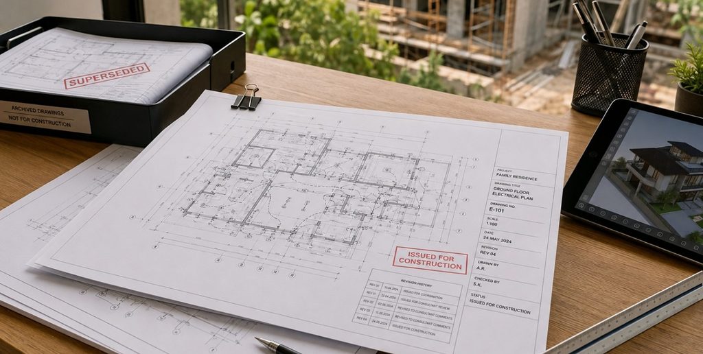
Every issued construction drawing should clearly identify:
- Project name
- Drawing title
- Drawing number
- Scale
- Date
- Revision number
- Revision description
- Designer/engineer
- Approval or issue status
- “Issued for Construction” status, where applicable
Construction should never proceed from preliminary, superseded, or unapproved drawings.
19. Make Sure Site Teams Have the Latest Drawings
Even a fully coordinated design can cause problems on site if different contractors are working from different revisions.
- Maintain one controlled drawing register
- Remove superseded drawings from use
- Issue revisions formally
- Record site instructions
- Obtain clarification for unclear details
- Avoid approving technical changes only through calls or chat messages
- Confirm subcontractors are working from the same revision
- Reflect approved changes across all related drawings
A small change to a bathroom, for instance, can ripple across architectural, structural, plumbing, electrical, and tiling drawings all at once, which is exactly why this coordination matters more than it might seem.
20. Request As-Built Drawings at Completion
As-built drawings record what was actually installed, which is different from what was originally planned once a project accounts for site adjustments. They’re useful for:
- Finding concealed pipes
- Locating underground drains
- Identifying electrical circuits
- Future repairs
- Renovations
- Extensions
- Installing new equipment
- Preventing accidental damage
- Property maintenance and handover
The final drawings should reflect approved site changes, not just the original design intent.
Common Problems This Stage Helps Prevent
| Poor coordination | Possible result |
| Column/furniture conflict | Reduced usable space |
| Beam/window conflict | Lower opening or altered façade |
| Unplanned AC drainage | Visible external pipework/staining |
| Poor revision control | Work built from outdated drawings |
Homeowner’s Pre-Construction Checklist
- Are the architectural drawings final?
- Do the structural drawings match the architectural layout?
- Has the structural design considered the soil and site conditions?
- Are columns and beams coordinated with rooms, windows, and doors?
- Has staircase headroom been checked?
- Are water tanks structurally supported?
- Do the electrical points match the furniture plan?
- Have kitchen appliances and sockets been coordinated?
- Are air-conditioning locations and drainage routes shown?
- Are water-supply and hot-water routes planned?
- Are wastewater and rainwater systems shown separately?
- Is the septic or sewer arrangement confirmed?
- Have plumbing and electrical routes been checked against structural elements?
- Are service openings planned before concreting?
- Have roof and site drainage been designed for heavy rainfall?
- Does every drawing show the latest revision?
- Have the relevant consultants reviewed the coordinated drawings?
- Has the latest coordinated set been formally issued for construction?
Final Thoughts
Structural and MEP drawings are not simply technical documents for consultants and contractors. They are where many of the practical decisions that determine how comfortably, safely and efficiently a house can be built are resolved.
For homeowners, the key is not to interpret reinforcement schedules or engineer the building themselves, but to make sure the architectural, structural and service designs have been properly coordinated before work begins.
In Sri Lanka, that coordination is particularly important when considering rainwater drainage, water storage, power systems, sewer or septic arrangements and local approval requirements.
At Top Living, these disciplines are coordinated as part of the wider design and construction process so that technical decisions can be resolved before they become expensive changes on site.